               Hyper+ XF 1.0 MANUAL (c) 1998 S.Dorndorf

Note: this german to english translation was done with the help of
BABELFISH. So there are quite many errors and mistakes, as well as
non-translated german words. I was much to lazy to translate it all
by hand or to correct the full Babelfish text. Thus, give it a
good laugh when reading this sometimes funny translation...
(Laufwerk=drive, M?glichkeit=possibility, Unterst?tzung=support,
 n?chste=next, f?r=for, L?nge=length, mu?=must, etc. etc.)
1 introduction
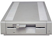
The Hyper-XF ROM 1.0 is an upgrade for the ATARI floppy disk drive
XF551. There are two versions: a) Hyper-XF 1.0A for the original XF
with 5,25"drive and b) Hype-XF 1.0B for converted XF with 3,5" drive.
After the installation, which is very simple, lots of additional
functions are aivalable:
- quicker floppy Speeder (ultra speed and hyperspeed)
- bootable hyperspeed driver in the ROM
- partition administration (four partitions on a 3,5"-disk)
- inserted boot menu to boot of partitions and shop the
hyperspeed driver
- improved double Density recognition
- command for reading from ATARI ST or PC double Density disks
- commands for TRACK analysis
- command for formatting arbitrary special format
(known as sector skewing)
- commands for copying copyprotected disks
- possibility for the installation of an automatic density recognition
(similar to the 1050 floppy)
Furthermore, the many small errors of the original-XF551-ROM were
eliminated. The Hyper-XF always writes without Verify to disk. The
Verify is anyway very slow and therefore used by no more DOS. It is
unfortunately not possible to format in High Density.
After switching on the Hyper-XF behaves in the same way like the
normal XF551 OS, but it gives the following differences:
- the Hyper-XF recognizes double Density disks during the
reading now also
- disks can be formatted, read and written in all three densities
(single, medium and double), as well as 360k and 720k.
- now supports ultraspeed and hyperspeed instead of XF highspeed.
2 Installation of the Hyper-XF ROMs
The Hyper-XF ROM is present on an 8KB-EPROM-Chip and is a replacement
for the original ATARI XF ROM. Right on the label of the Hyper-XF ROMs
you can read the version number: A is meant for 5,25" drives and B for 3,5"
drives. Never use the B-version with a 5,25" drive!!
To the installation you go forwards as follows (for the change in a 3,5"drive
see also chapter 3): - unscrew the four screws on the lower surface of the
XF - take off plastic top of the XF - unscrew the four screws, which connect
the metal angle of the 5,25" drive with the the XF lower part - lift the drive
assembly carefully to the side, so you can see a chip with 28 pins - if needed
take off the flat cable (but remember the polarity!) - lever the chip with the
28 pins with a screwdriver carefully from its base - put the Hyper-XF ROM
into the base; NOTE: Do not touch the pins of the ROMs with your fingers,
to avoid magnetic polarity (and possible destruction of the chips);
The notch at one of the narrow sides at the Hyper-XF ROM must fit
to the drive assembly front show. Wrong installation may cause
malfunction or even destruction of the ROM. - now install the drive
assembly again and bolt on - check whether the flat cable at the drive
assembly sits correctly - then take the plastic top again and fit it
to the drive and again bolt on. Thus the installation is completed.
For a test stick on the cables to the XF551 and switch the XF on.
Whenswitching on, the write head should move a little inward and again
moveoutward, if not an error is present. Setup the XF with the rear left
DIP switches to drive number #1 (both switches down) and then switch
the drive and right afterwards the ATARI XL/XE on (without a disk in the
XF). If the boot Menu with the copyright notice appears, the Hyper-XF
is fully operational.
3 changes for a 3,5" drive
The XF551 can be changed easily to a 3,5" drive. Therefore you will
need the following things: - a 3,5" drive (approx. 20 Dollars / 24
Euros) - a 5,25" mounting case for 3,5" drives (approx. 3 Dollars, 4 Euros)
- a current cable connection to convert the standard 5,25" drive cable
for the 3,5" drive - possibly a longer flat cable for the 3,5 drive
(approx. 20cm); NOTE: When purchasing a 3,5" drive pay attention, that
the drive configures as drive A: (not B:), otherwise you may have to
change a jumper in the drive assembly change, so that the XF functions
correctly.
The installation turns out as follows: - the 3,5"-Laufwerk with the
4-6 provided screws at the bay fasten - the four screws at the lower
surface of the XF551 unscrew - Geh?usedeckel take off - the flat cable
and the current supplying us cable of the 5,25"-Laufwerk take off
(note polarity before)
- the four screws, which hold the 5,25"-Laufwerk at the metal angle,
unscrew and the 5,25"-Laufwerk away-put - now the hyper+ XF ROM 1.0B
into the XF to build, see chapter 2. - the 3,5"-Laufwerk with the
four screws to the metal angle fasten - which inserts put on the
Anschu?leiste in the back at the 3,5"-Laufwerk - the flat cable on the
insert put NOTE: Polarity absolutely consider: The red marked cable
at the flat cable mu? on the Anschlu?beinchen 1 of the 3,5"-Laufwerks
to be put. The Beinchen 1 is mostly marked by " 1 " on the
3,5"-Laufwerksplatine. - the current cable connection to the current
supplying us cable f?r the 5,25"-Laufwerk attach and to the
3,5"-Laufwerk anschlie?en. This is only in a polarity m?glich, thus
no force uses. - Geh?usedeckel on present and bolt. Thus the change
is completed, for a test proceed as in chapter 2.
4 Ultra speed
The Hyper-XF uses Ultra speed, which alters the Baud rate between
the computer and the drive from 19200 bps (standard) to 57600 bps
(ultra/hyper speed), which is even faster than XF highspeed (with
38400 bps). Ultra speed is also used by Happy 1050 and Speedy 1050
enhancements and has become a de-facto standard in the ATARI 8bit
world. Thus ultra speed is supported by most XL/XE OS extensions
(e.g. QMEG-OS, SPOS, US+OS, etc.) and many DOS versions (e.g.
XDOS, Bibo DOS, Turbo-DOS XL/XE, Sparta DOS, Super DOS, etc.). So
the XF becomes three times faster than in normal operation mode.
For the utilization of the high data transfer however, disks
must be formatted (as with the normal XF551 or USD) in a special
"sector skewing format". This happens automatically, if the OS or the
DOS sends the formatting command in Ultra speed to the drive assembly
(the QMEG-OS 4.04 does). Otherwise you should use a program, which
permits it, to use ultra speed and formats with sector skew (for
Sparta DOS you can use XINIT.COM).
5 Hyperspeed
If you use no OS or DOS with ultra speed support, you can also use
hyperspeed to begin. Hyperspeed is just as quick as Ultra speed, it
has however two advantages: First, many DOS versions with XF551
supportcan be patched easily for the use of hyperspeed. Second, the
Hyper-XF menu already contains a hyperspeed driver, which can be
loaded before a disk is booted with the ATARI. Simply boot your
computer without a disk in the drive (the Hyper-XF should be setup as
drive 1). The following menu appears on the screen:
Hyper+ XF 1.0x (C) S.Dorndorf
Mode=X ABCDMFSX
Boot? E16
Now insert a disk and press one of the indicated keys of the menu
besides "BOOT?": (1) the hyperspeed driver is loaded and booted in the
RAM of the XL/XE on the upper half of PAGE 1 ($100-$17f) and the disk
loads with hyperspeed. (6) corresponds to (1), the hyperspeed driver
however is loaded into the upper half of PAGE 6 ($600-$67f) and the
disk loads with hyperspeed. (ESC) The inserted disk is booted normally
without any hyperspeed driver. The indicated BOOT ERROR is intended,
because it represents the only way to arrange the ATARI to boot off
the inserted disk.
The program loaded from the disk may overwrite the hyperspeed driver
in the memory on PAGE 1 or PAGE 6. In this case the computer will
lock up and crash. Try simply both variants out, normally functions (1).
With (6) quite many programs will crash, which do not adhere to the
ATARI guideline, to keep PAGE 6 free for the user.
For formatting apply the same rules like for Ultra speed: For the
utilization of hyperspeed the disks m?ssen to be particularly
formatted. This happens automatically, if the formatting command is
sent by the DOS in hyperspeed (the DOS Patches erw?hnten above to
do all this).
6 diskette format
The hyper+ XF unterst?tzt by the standard formatting command,
which each DOS uses, altogether 12 different formats:
It can be formatted in single Density (SD), medium Density (MD) or
double Density (dd). All formats k?nnen to be produced alternatively
on one side or bilaterally: With the one-sided format also with
3,5"-Laufwerken only 40 TRACKS are formatted, always formatted with
the bilateral format the whole disk. Zus?tzlich can be formatted each
format in the normal variant or in the Ultra speed variant.
With 3,5"-Laufwerken it is better to use DD disks to HD disks
functions, if the HD hole is sealed, it also k?nnten however more
sp?ter to read errors f?hren (so far I had itself still no problems).
In High Density (1,4MB) cannot be formatted.
7 Density recognition
The hyper+ XF recognizes grunds?tzlich during the reading of a sector
the density of the inserted disk. If you call with a DOS without XF
Unterst?tzung after a disk change of SD or MD on dd or turned around
the directory, then folds only with the second attempt. Changing from
SD on MD or goes in reverse problem-free, since the Sektorl?nge does
not?ndert itself. With DOS version, those with the sector 1 (Sparta
DOS) give it against it no problems with the Density recognition read
a open file.
The hyper+ XF offers however the possibility to insert a contact at
the drive assembly flap so there? the Density recognition as with the
1050 fully automatic functions. To the installation mu? however in
the XF to be gel?tet: Pin 35 of the 8040/8050 (the chip with the 40
pins) into the XF more?ber a tracer with mass (e.g. pin 14 of the 1772
or the pin 20 of the 8040/8050) connect. The tracer mu? in the drive
assembly mechanism so to be fastened, there? the tracer is closed, if
the drive assembly lever is open. Suitably f?r 5,25"-Laufwerke is
e.g. the mushroom head tracer Best NR. 704687 from the offer of
Conrad.
8 partitions and operatings mode
The hyper+ XF offers altogether eight different operatings mode, which
specify like the hyper+ XF disks access. To?ndern the operating mode
boats it the hyper+ XF without disk, on what the boat Men? appears.
Right beside " MODE= " the up-to-date stopped operating mode stands.
By Dr?cken one of the keys ABCDMFSX is ge?ndert the mode. With the
keys ESC (or 1 or 6) then an inserted disk can be gebootet.
There are the following operatings mode:
Mode X: (XF mode) this mode is active after switching on of the
hyper+ XF on. It corresponds to the normal XF551-Betrieb.
Mode S: (ST /PC /HDI standard mode) serves for the access to
double-sided disks in the old standard format, as it is used e.g. by
the HDI. In this mode disks do not k?nnen in the ST or PC format to
be read, letters go however also with special command. The s-mode
differs from the x-mode only by the format on the backside of the disk
(the XF551 stores the sectors on the backside " wrongly around ",
e.g. the current sector 721 in the s-format on TRACKS 0, sector 1, in
the x-format against it on TRACK 39, is sector 18 with a
5,25"-DD-Disk).
NOTE: The hyper+ XF does not pr?ft after, in which mode a disk was
formatted. Use therefore the mode S only, if absolutely needed (in
order e.g. one with the HDI formatted double-sided DD disk to read)
and you switch thereafter immediately back into the x-mode.
Mode M: (multi) in this mode the XF divides the inserted disk in
partitions. On each partition you can contents of a
5,25"-Diskseite (alternatively SD, MD or dd) accommodate and with
each DOS work on. With 5,25"-Disketten two partitions (A and B) are
avaiable,whereas four partitions (A, B, C and D) are avaiable with
3,5"-Disketten.
On the partitions you k?nnen with ascending drive numbers
access (abh?ngig of the switch attitude in the back on the drive
assembly). E.g. if the XF is adjusted as drive assembly #1, then
become with a 3,5"-Laufwerk with D1: to D4: the partitions A to D
addressed. Become accordingly with 5,25"-Laufwerken of?ber D1: and
D2: the partitions A and B addressed. Quasi two and/or four drive
assemblies stand to the Verf?gung, which is zusammengefa?t on a disk.
Thus you k?nnen with each DOS on the entire disk access, especially
the partitions k?nnen also in densities to be formatted. Or you copy
with a disk copier, which zul??t the selection of several drive
numbers, which data disk side of " Alternate Reality - The Dungeon "
on a 3,5"-Disk together, which makes diskette change?berfl?ssig when
playing. NOTE: Under the drive number f?r the partition A (D1: in
the above example) you k?nnen also exactly as in the mode X on the
whole disk access. Thus a h?ufiger change between the modes X and
M is avoided. If you want to format all partitions in the same density,
k?nnen instead also the drive assembly f?r the partition A on both
sides to format, goes more quickly. The hyper+ XF cannot recognize
partitionierte disks automatically. They m?ssen thus even pay
attention not to write e.g. to partition B if one not partitionierte
disk is inserted.
Mode F: (format multi) mode corresponds to M, however the hyper+
XF tests automatically with each partition change the density of the
partition. It erm?glicht to also change without special software
between differently formatted partitions. NOTE: With differently
formatted partitions an inserted contact at the drive assembly flap is
set for automatic Density recognition au?er combat, since the disk
was not changed.
Mode A,B,C,D: (partition mode) hereby can be accessed under the
drive number stopped in the back at the drive assembly the appropriate
partition A to D. With 5,25"-Laufwerken C and D correspond to the
partitions A and B. are e.g. the XF as drive assembly #1 adjusted,
have you hereby the M?glichkeit, each gew?nschte partition to boats.
9 SIO commands
In the following chapters all SIO commands of the hyper+ XF are
erkl??rt. This is above all f?r a programmer with machine language
knowledge interesting, which writes utilities f?r the hyper+ XF
m?chten.
Zun?chst some Erl?uterungen: A diskette side has 40 traces (TRACKS)
(with 3,5 ": 80 TRACKS). Each TRACK is normally divided for his part
when formatting in 18 sectors (with MD there is 26 sectors).
Logical TRACK and Sektornr: The logical TRACK No. goes from 0 to 79
(3.5 ": from 0 to 159). The logical TRACK No. is more gr??er than 39
(3.5 ": more gr??er than 79) the hyper+ XF accesses automatically on
the correct TRACKS on the second disk side. The logical sector No.
corresponds in the s-mode to the physical sector No., in all other
modes is always however the sectors (and the TRACKS) on the
Diskr?ckseite " wrongly around " put down, in order to be compatible
to the Original-XF551. E.G. f?r SD and dd apply: The sector 1
corresponds to the physical sector 18, sector 2 corresponds to that
physical sector 17 etc.. The hyper+ XF expects TRACK and sector data
always logically, with which conversions are not necessary on the part
of the programmer.
current Sektornr: The normal numbering of all sectors
starting from 1. It applies f?r to SD and dd the following
conversion, f?r MD mu? the 18 by 26 to be replaced: lfd.Secnr =
log.Tracknr * 18 + log.Secnr
In the following f?r all SIO commands become in each case - the
command byte ($302), - the I/O Datenrichtung ($303: 0=No DATA,
$40=receive, $80=send), - the number of the data byte ($308/9) and -
the AUX1/AUX2-Bytes ($30a/b) indicated:
10 XF551-Kommandos
Command: R ($52) function: (READ second gate) DATA I/O read sector:
Receive 128/256 byte AUX1: current Sektornr. (Low byte) AUX2:
current Sektornr. (High byte) or AUX1: logical Tracknr. AUX2: $$C0
plus logical Sektornr. or AUX1: logical Tracknr. AUX2: $$FF
(reserve sector reads) reads the indicated sector of disk. 128 (with
SD and MD) or 256 bytes (with dd) is sent to the computer. With the
current sectors 1 to 3 also in dd only 128 byte is sent.
The gew?nschte sector can be indicated also in form of the logical
TRACK and sector No. (AUX2>=$C0). Is AUX2=$FF becomes sucked.
Reserve sector (see e-command) of the indicated TRACK read. The
AUX2-Werte $$FC to $$FE is f?r internal functions (boat Men?) the
hyper+ XF reserves.
Command: P ($50) function: (PUT second gate) DATA I/O write sector:
Send to 128/256 byte) AUX1/2: as is the case for command R
Writes the data on the indicated sector on disk. Corresponds to the
ansonstem R-command.
Command: W ($57) function: Sector write (Write second gate)
corresponds to the p-command.
Command: S ($53) function: DATA I/O read status: Receive 4 byte
AUX1: without meaning AUX2: Density check level: " = status only
(no check) " T " ($54) = test engine (check only, if engine out) " U "
($55) = Unconditional (check in any case) otherwise = check on error
(check only in the case of error)??ber AUX2 one can indicate S " ($53)
whether and in which case the hyper+ XF the density of the inserted
disk is to pr?fen. This is interesting if no Density recognition is
built into the drive assembly. The drive assembly sends 4 bytes,
which contain the momentary status of the drive assembly:
1.Byte = DRIVE status
Bit 0: Last command incorrectly bit 1: Last data block incorrectly
bit 2: Last disk read/write access incorrectly bit 3: Disk
write protected bit 4: Engine still works bit 5: Double Density bit
6: next formatting instruction formats on both sides bit 7:
Medium Density
Bit 3 is valid only if with the last disk access the wanted
sector on the disk were present. Bit 6 can be set more?ber the
o-command and after everyone of the six commands RPWutc is
set back, in order to avoid false formatting.
2.Byte = status of the floppy CONTROLLER (FDC) bit 0: / BUSY
CONTROLLER works still bit 1: / DRQ service request of the FDC
unanswered bit 2: / LD CONTROLLER data went lost bit 3: / (carriage
return character) checksum-error bit 4: / RNF sector not found bit
5: / blank record type " Deleted " bit 6: / WP write-protect bit
7: / OPEN no disk in the drive assembly
This byte indicates, which errors arose with the last access to a disk
sector. All bits are Low active. Bit 7 is g?ltig only if the
automatic Density recognition were built into the XF. Hier?ber can be
queried also the most diverse error sector, the following variants are
m?glich:
$$FF OK $$FB LD $$F7 (CARRIAGE RETURN CHARACTER) $$F3 LD+CRC $$DF
BLANK $$DB LD+RT $$D7 RT+CRC $$D3 LD+CRC+RT $$EF RNF $$E7 RNF+CRC
3.Byte = Timeout value for formatting ($$D9) this byte can be also
used, in order to query whether the addressed drive assembly is a
hyper+ XF. Furthermore stands for Ultra and High speed in the lower four
bits the SIO Transferrate f?r (see also the?-command).
4.Byte = operating mode and type of drive assembly
Bit 7: reserved (always 0) bit 6: 0 = 5,25"-Laufwerk 1 =
3,5"-Laufwerk bit 5: reserved (always 0) bit 4: With the next
disk access Density checks execute bit 3: reserved (always 0) bit
210: Operating mode: ABCDMFSX value: 01234567
Bit 4 is set whenever with the last disk access the wanted sector
is not found. That can happen only if the sector is defective, is not
not formatted the disk or no disk lies in the drive assembly. With
the s-command a Density check is executed if AUX2 is not equal to
" S ".
Command: ($21) Function: Disk/partition in SD or dd formats DATA
I/O: Receive 128/256 byte AUX1/2: without meaning
Formats a disk and/or a partition - depending upon adjusted operating
mode.
The density (SD or dd) and the page number (one-sided/bilateral) must
before more?ber the o-command to be adjusted. If the density is
adjusted to MD, in SD one formats. It is always formatted with
Verify, in order to recognize incorrect disks equal when formatting.
Command: " ($22) function: DATA I/O format disk/partition in MD:
Receive 128 byte AUX1/2: without meaning
Always formats the disk in MD. The side's number must before with the
o-command to be adjusted. Corresponds otherwise to the!-command.
Command: N ($4e) function: Vintages of the Config block (IN PUT
Config block) DATA I/O: Receive 12 byte AUX1/2: without meaning
The 12 byte of the PEROM config. table is sent to the
computer, which was adjusted last more?ber the o-command:
Byte 0: TRACK amount of (40 and/or 80) byte 1: Step rate in ms (6
and/or 3) byte 2: Sectors for each trace REAR ONE (always 0) byte 3:
Sectors for each trace LO (18 and/or 26) byte 4: Side amount of (0
or 1) byte 5: Formatting procedure (0=FM, 4=MFM) byte 6: Byte for
each sector REAR ONE (0 or 1) byte 7: Byte for each sector LO (128 or
0) byte 8: Drive assembly actively (always 255) byte 9-11: unused
(always 0)
Command: O ($4f) function: (output Config block) DATA I/O write
Config block: Send 12 byte AUX1/2: without meaning
The 12 bytes of the Config block are sent to the drive assembly. For
the meaning of the bytes see n-command. The o-command is used, over
before formatting with the commands! to adjust and " the density and
side's number correctly. The hyper+ XF determines the format from the
bytes 5, 6 and 7, all other bytes is ignored. Nevertheless the bytes
0 and 2-7 should be always set.
After executing one of the commands RPWutc is always set the byte 5 of
the Config block zur?ck to 0. Thus one avoids, there? a disk is
formatted on both sides by mistake. Byte 5 does not have influence on
reading and writing from disk sector.
11 speed Y-command
Command: ($3f) Function: DATA I/O read SIO speed byte: Receive 1
byte AUX1/2: without meaning
A byte is sent to the computer ($09), with which the computer is
adjusted to the high Datatransfer (Ultra or hyperspeed).
This is done via registering the byte in $$D204. With Ultra speed
data must be transfered with this command in high datatransfer.
With hyperspeed mu? the command byte with set bit 5 and 7 to
be sent and after the receipt of the command AK byte to the high data
rate be switched. Hyperspeed corresponds to 5 in the command byte of
the Original-XF551-High-Speed up to the higher data rate and setting
bits.
Command: Space ($20) function: DATA I/O format disk/partition in the
background: NO DATA AUX1/2: If AUX1=$11 and AUX2=$04 are formatted
in MD
Corresponds to the!-command with the following differences: If
AUX1=$11 and AUX2=4 are, in MD one formats. After formatting the
first TRACK the computer sends back a COMPLETE . The
computer can continue working now, while the drive assembly still
formats. With the s-command it can be determined later
whether formatting was successful. This command is e.g. for a disk
copier useful, in order to format while reading the source
diskette in at the same time the target disk in another drive assembly.
Command: f ($66) function: DATA I/O format disk with certain sector
order: Send 128 byte AUX1/2: without meaning
128 bytes are sent to the drive assembly. The first 12 byte
corresponds to the Config block (see o-command), the next 18
and/or 26 bytes specifies, into which order the logical sectors on the
TRACKS are put down. The optimal sector sequence is different
depending upon density, e.g. the sequences are for the normal speed
format as follows:
SD: 1.3.5.7.9.11.13.15.17.2.4.6.8.10.12.14.16.18 (Sector-Skew=10) dd:
6.12.18.5.11.17.4.10.16.3.9.15.2.8.14.1.7.13 (Sector-Skew=16)
12 hyper+ XF commands
Command: c ($63) function: (Configure mode) DATA I/O stop operating
mode: NO DATA AUX1: Bit 2-0: Operating mode (corresponds to
01234567 ABCDMFSX) bit 4: 1=Density-Check with the next disk
access AUX2: without meaning
Hereby the operating mode is stopped.
Command: e ($65) function: Universal formatting (Extended format)
DATA I/O: Send 128 byte AUX1: logical No. of the TRACK = $$FF whole
which can be formatted disk/partition format $$FE = as $$FF, but in
the background AUX2 formats: Bit 7: 1=ohne, 0=mit Verify format
With this command any format on the disk can be produced. Apart from
the data in AUX1 and AUX2 must be 128 byte a long format block with the
following format data to the drive assembly to be sent:
Byte 0-11: To Config block, see o-command
Byte 10: Sector Skew byte bit 0-4: Sector sequence 0 = from sector
table 1-$19= take Sector Skew indication (it gives on how many sectors are
to lie between two successively numbered sectors) $1a = for normal speed
to compute $1b = for normal speed (optimized) $1c= optimized for Warp speed
$1d = optimized for Ultra speed $1e = optimized for HDI format $1f =
optimized for turbo-DRIVE bit 65: Reserve sector 00 = no place specifies
for reserve sector lets 01 = with place for reserve sector format to 10 =
with additional reserve sector to format without meaning, if bit 0-4 >=$1A
bit 7: reserves, 0 bits
Byte 11: Second gate length byte $00 = take Sektorlengths from
length table $01 = Sektorlength in accordance with ?? Bits
5-6 of byte 10 compute $20-$df = direct indication of the Sektorlength
in FM byte
Byte 12-56: Sector table each byte in this table corresponds to a
sector: Bit 0-4: Sector number bit 765: Error status of the sector:
101 = sector with LD error 110 = sector with RNF+RC error otherwise =
sector without errors
Special value in the sector table: $$C0 = gap format (only
if byte 11 = 0) $00 = marks the end of the sector table
Byte 60-103: Length table indicates the length to each sector and/or
gap from the sector table in FM byte. A FM byte corresponds to 1
byte in SD, in MD and dd 2 bytes on the disk. For a sector are lengths
of $20-$df valid, for a gap lengths of 1-$FF. A sector always
consists of 32 FM byte for the sector header and under normal
conditions of 64 or 128 FM byte for the sector data. In addition
may still some gapbytes come. The sum of all bytes in the
Lengthtable must not be longer than 3232.
If a wrong value should be located somewhere in the format block, this
before the engine starts with an error 144 is acknowledged.
Command: g ($67) function: TRACKS analyze (GET TRACK info.) DATA
I/O: Receive 128 byte AUX1: logical Tracknr. AUX2: Analysis level:
$00 = complete Scan $20 = test only sector header otherwise =
test only sector contents (AUX2 mu? To sector Skew of the disk
contained, see byte 10 of the format block) with this command the
given TRACK one analyzes. The drive assembly sends 128 byte to the
computer, which corresponds to the format block of the e-command in
their structure exactly. The density of the TRACK is not tested,
therefore mu? before the g-command the correct density adjusted its.
F?r the received format block applies: Byte 10 and 11 are always 0.
The following meaning has the bits 7-5 of the bytes from the sector
table: 000 = sector OK ONE and empty (filled with zeros) 001 = raw
component error 010 = RC ERRORS 011 = RT+RC errors * 100 = sector is
short (too few data byte has), has an RC ERROR and possibly still
another raw component error * 101 = LD errors, possibly also (CARRIAGE
RETURN CHARACTER) and/or raw component error * 110 = RNF+RC errors 111
= sector of OK ONE and not empty
The Sektorheader test determines only with * marked error sector
and determines the Sektorlengths. The remainder is determined by the
Sektorcontents test.
The format block received with the g-command can serve
without change as input f?r the e-command. That serves copying
copy-protected disks together with the commands t and u.
Command: t ($74) function: Error sector in SD and MD read (TRACK
READ) DATA I/O: Receive 128/129/256 byte AUX1: logical Tracknr.
AUX2: Bit 4-0: logical Sektornr. Bit 765: Read mode 000 = normally
read (only SD/MD) 001 = RT/RC/LD errors ignore (only SD/MD) 010 =
RT/RC/LD errors ignore (only SD/MD) and CONTROLLER status as 1.Byte
100 = first half of a 512-Byte-Sektors send read 110 = second half
read
With this instruction error sector does not to be quickly read,
the hyper+ XF makes in the case of an error a repeating attempt in SD
and MD, how it is with the R-command the case. 128 byte is sent to
129 byte to the computer, with the variant 010 is it. Furthermore
can the 512-Byte-Sektors of a DD disk by the ATARI ST or a PC in two
be read in two halfs.
Command: u ($75) function: Error sector in SD and MD write (update
second gate) DATA I/O: Send 128 byte AUX1: logical Tracknr. AUX2:
Bit 4-0: logical Sektornr. Bit 765: Type of error: 000 = normally
001 = blanks 010 = (carriage return character) 011 = RT+CRC 100 = LD
without (carriage return character) 101 = LD+RT without (carriage
return character) 110 = Short second gate (last data byte enth?lt
number of bytes which can be written) 111 = Short second gate with
blank
Writes an error sector on the disk. 128 byte is sent to the drive
assembly.
13 disk utility
Around the Possibilities of the hyper+ XF to use correctly it requires
still some disk utility:
- disk copier for quick copying of arbitrary disks - TRACK copier for
copying copy-protected disks - disk map by for the quick scanning
of a disk - patched DOS and Game DOS (hyperspeed, operatings mode)
- DOS Formatter (suitably for all DOS versions) - ST/PC disk readers
for reading from files of the PC or ST
________________________________________________________
Download ROM pre 5.25" floppy mechaniku: 
HYPROMA.rom (8,00 kb)
Download ROM pre 3.5" floppy mechaniku:
HYPROMB.rom (8,00 kb)
__________________________________________________________

Vaše hodnotenie, Rate post: